

July 8, 2026
360° Panoramic Image Coordinate System and Local View Mapping Technology
Author
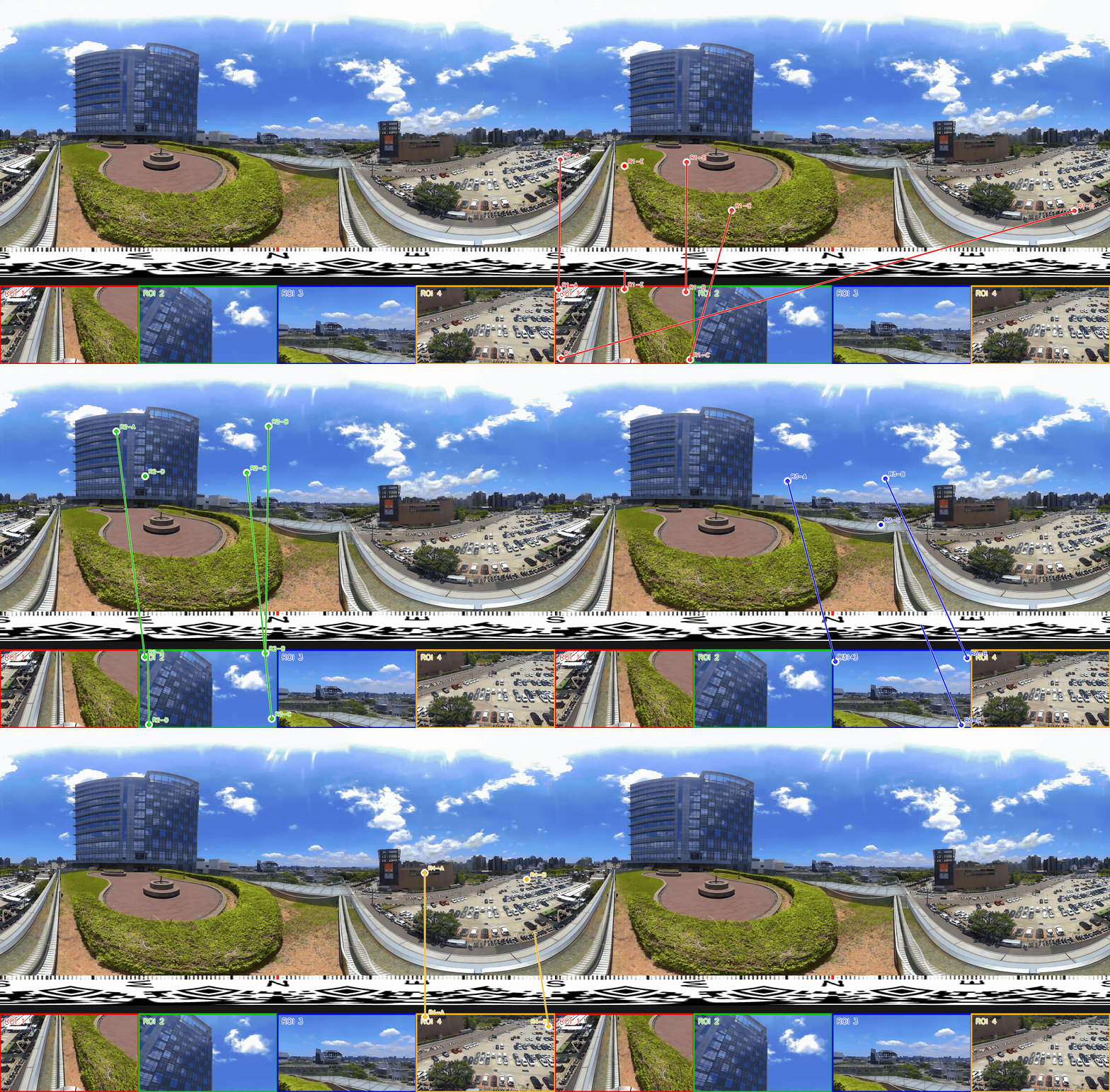
As 360° panoramic cameras become increasingly widespread in smart surveillance, remote inspection, construction site safety management, and smart building applications, "being able to see everything" is no longer the challenge. The real challenge is: how do we pinpoint every local detail from that full view, and map that detail information back to the full view? When a system crops a specific region out of a 360° panoramic image to provide local viewing, AI object detection, event annotation, or remote inspection features, a core technical question arises: how can the coordinates in a local view be correctly and instantly mapped back to the original 360° panoramic image?
This seemingly simple coordinate-transformation problem actually involves multiple layers of technology: spherical geometry, camera projection models, and image resampling. It is also the key piece of infrastructure that determines whether an entire 360° imaging application system is actually usable. This article starts from real-world pain points, dives deep into the design principles behind Cupola360's coordinate-transformation technology, and explains how this technology delivers concrete value for safety monitoring, AI detection, and operational decision-making.
The Gap Between "Panoramic Viewing" and "Local Application"
Traditional 360° panoramic imagery has mostly been used for browsing — users drag the screen to look around the scene and get an immersive spatial experience. In real commercial and industrial application scenarios, however, 360° imagery has long since stopped being just a "viewing" tool — it now serves as a data source that feeds massive backend computation and AI analysis.
Common application scenarios include:
- Remote inspection: Inspectors review equipment status region by region through local views, rather than continuously manipulating the entire panoramic sphere.
- AI object detection: AI models perform person detection, equipment recognition, or anomaly detection on cropped local images (e.g., a horizontal, angle-specific perspective view), because most off-the-shelf object detection models are trained on "perspective projection" images and are difficult to apply directly to spherical/equirectangular-projected panoramic images.
- Event annotation: When a manager clicks on an anomalous position in a local view, the system needs to record where exactly that event is located within the entire space.
- Multi-view integration: A single site may have multiple 360° cameras, multiple local views, and multiple sets of AI detection results running simultaneously — all of this information ultimately needs to converge onto one unified spatial coordinate reference to be managed and tracked effectively.
In other words, the value of a 360° imaging system doesn't lie in simply presenting "the panorama" — it lies in having bidirectional correspondence between the panorama and its local views. That is exactly the coordinate-transformation technology this article explores.
The Pain Point:
The "Disconnect" Between Local Views and the Panoramic View
- In systems that lack a precise coordinate-mapping mechanism, the local view and the panoramic view often end up as two entirely separate coordinate systems, creating the following practical problems:
- Time lost: Difficulty locating events When AI detects an anomaly in a local view (e.g., an intruder, overheating equipment, a left-behind object), if that coordinate cannot be restored to its actual position in the panoramic image, managers cannot quickly determine "which corner of the site this anomaly actually occurred in" — they're often forced to manually compare footage and guess the location based on experience.
- Duplicate alerts: Difficulty tracking across views In a site with multiple cameras and multiple local views operating at once, the same object or event may appear across several different local views. Without a unified coordinate reference, the system cannot determine whether detections in these different local views refer to the same event, leading to duplicate alerts or broken tracking.
- High cost, low accuracy: High cost of manual comparison and calibration To work around these issues, many teams resort to manually cross-checking the relative position between local views and the panoramic view — a process that is not only time-consuming but also prone to error from subjective judgment. Over time, this drives up operational costs and reduces the real-time responsiveness of inspection and monitoring.
- Limited AI value: AI applications are limited in value If an AI detection model's output is confined to a bounding box within a single local view, its commercial value is quite limited. Only by mapping detection results back into the full spatial coordinate system can they support higher-level applications such as heat-zone analysis, movement-path tracking, and cross-camera event correlation.
Technical Principles:
The Core Logic of Coordinate Transformation
To solve the pain points above, a system must establish a rigorous geometric correspondence between the local perspective view and the 360° panoramic image. This transformation logic can be broken down into the following steps:
- Establishing the View's Center Direction
360° panoramic images are typically stored using Equirectangular Projection, where the image's horizontal axis corresponds to azimuth (yaw, ranging 0°–360°) and the vertical axis corresponds to elevation (pitch, ranging -90°–90°).
When the system crops a local region out of the panoramic image, the first step is to calculate the "center direction" of that local view based on its position within the panorama — that is, the horizontal angle (yaw) and vertical angle (pitch) that this segment of the view corresponds to. This center direction is equivalent to a virtual camera mounted at the center of the panoramic sphere, pointed toward a specific direction.
2. Deriving the Field of View (FOV)
Once the view's center direction is established, the system calculates the actual horizontal FOV and vertical FOV of the local view, based on the angular width the local region spans within the panorama and the aspect ratio of the output frame. The purpose of this step is to make the proportions of the local view match the visual experience of a human eye looking at a perspective image, avoiding distortion caused by the sphere-to-plane projection.
3. Building a Pixel-Level Ray-Casting Model
This is the most critical part of the entire technique: every single pixel in the local view can be treated as a line of sight (a ray) originating from the virtual camera's center direction and pointing toward a specific direction.
Specifically, the transformation process involves three stages:
- Local coordinates → normalized perspective coordinates: The pixel coordinates (x, y) in the local view are converted into normalized planar coordinates centered on the view's center direction, based on the frame's resolution and FOV.
- Perspective coordinates → 3D direction vector: Using the inverse of the perspective projection (the inverse of the gnomonic projection), the planar coordinates are converted into a 3D unit vector representing the actual direction this pixel points to in spherical space.
- 3D direction vector → panoramic image coordinates: This 3D direction vector is rotated according to the view's center direction (combining yaw and pitch), then converted back into horizontal and vertical angles under the equirectangular projection, ultimately mapping to the actual pixel coordinates (u, v) on the panoramic image.
Through this sequence of three computational stages, the system establishes a precise correspondence between every pixel in the local view and every pixel in the panoramic image — whether it's a position a user manually clicked, or a detection-box coordinate output by an AI model, both can be restored to the panoramic image's coordinate system using this same mathematical model.
4. A Unified Spatial Coordinate Reference
Ultimately, the value of this transformation mechanism lies in this: AI detection results, manual annotations, and event locations can all be uniformly mapped onto the same 360° panoramic image. Regardless of which local view, which AI model, or which capture operation the data comes from, as long as it can be restored to panoramic coordinates, it can be compared, overlaid, and tracked against a single spatial reference.
The Solution:
Cupola360's Coordinate-Mapping Capability
The Cupola360 platform implements the coordinate-transformation principles above as a real-time computation engine, eliminating the need for manual comparison between local views and the 360° panoramic image.
The platform operates as follows:
- Real-time bidirectional conversion: When a user clicks a specific position in a local view, or an AI model detects an object in a local image (such as a person, vehicle, anomalous item, or equipment malfunction), the platform instantly converts that local coordinate back into the 360° panoramic image's coordinate system.
- Annotation on the panoramic view: The converted coordinates are directly marked on the panoramic view, allowing managers to grasp an event's actual location within the entire site at a glance, without needing to switch between views.
- Multi-source integration: Local views captured from different angles and regions, along with detection results from different AI models, are all integrated into the same spatial coordinate reference through this single conversion mechanism, preventing information from becoming siloed within individual local views.
- Architectural flexibility: This conversion mechanism can accommodate local views captured at various angles and output aspect ratios — whether it's a fixed-position inspection view or a local view dynamically generated by AI tracking, the same coordinate-restoration logic applies.
Through this design, Cupola360 ensures that "local detail" and "the panoramic space" are no longer two disconnected sets of data, but rather one integrated system that can be cross-referenced and verified against each other in real time.
Application Scenarios
This coordinate-mapping technology applies to a wide range of scenarios that require "local observation, panoramic localization," including but not limited to:
- Smart construction site and safety management: Detecting violations such as missing hard hats or missing reflective vests via local views, and restoring the event location onto the construction site's panoramic map, so safety personnel can respond quickly.
- Campus and building security monitoring: Integrating AI detection results for access control, vehicle entry/exit, and abnormal crowd gathering into a unified 360° spatial map of a building or campus.
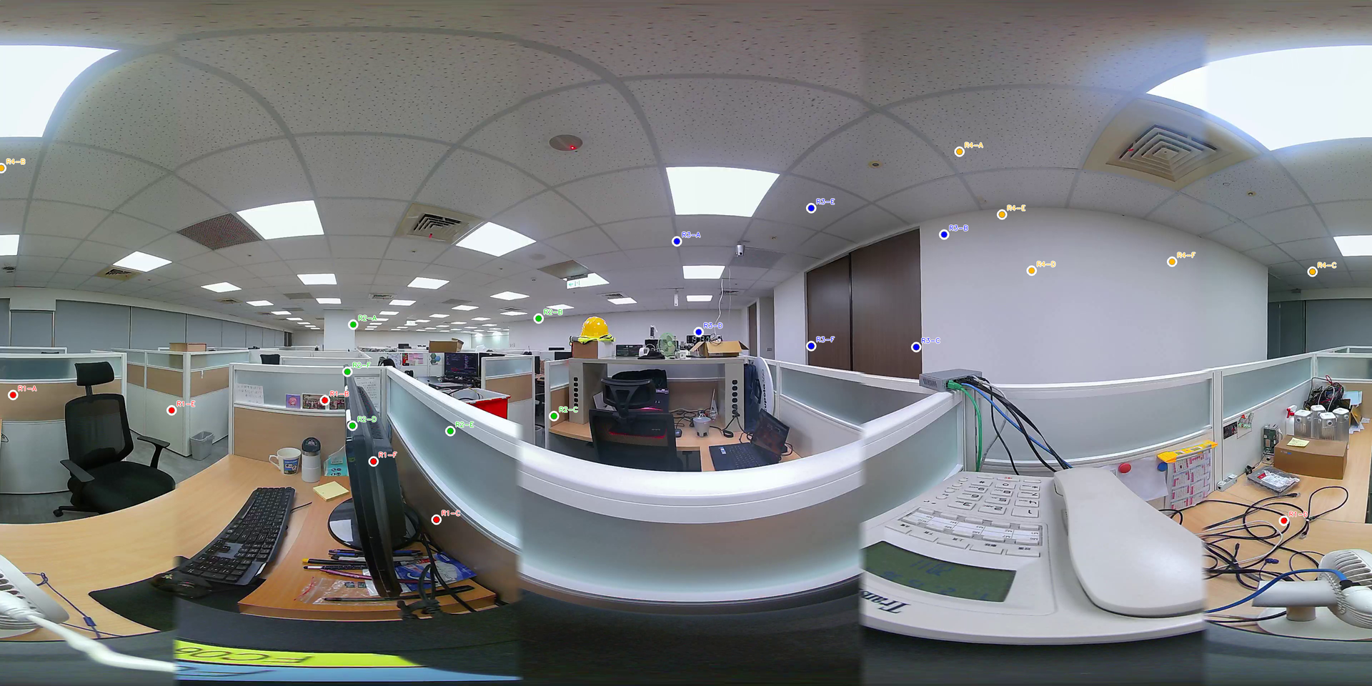
- Equipment room and office space inspection: For example, managing the large number of devices, cables, and labeled points within an office equipment room — coordinate mapping precisely correlates each inspection record and equipment status with its actual location in the site, making future tracking and maintenance scheduling easier.
- Remote meetings and spatial collaboration: When multiple people annotate issues from different local views, the system can synchronize all annotations onto the same panoramic image, avoiding miscommunication.
From a Single View to a Complete Site Perspective
The benefits delivered by this coordinate-transformation technology can be viewed across three levels:
For operations teams, it significantly reduces the cost of manual comparison and coordinate calibration, making event localization more accurate and processing more efficient — no longer requiring guesswork based on experience to figure out where an anomaly actually occurred.
For AI applications, detection results are no longer confined to a single local view but can be restored to the complete spatial coordinate system of the site. This allows AI model output to further support higher-level spatial analysis applications such as heat-zone analysis, cross-camera correlation, and movement-path tracking — substantially increasing the usability and commercial value of AI detection results.
For management decision-makers, multiple local views, sets of AI alerts, and real-time on-site conditions can all be integrated and presented on a single 360° panoramic image, forming a "single view, full situational awareness" management interface. This delivers real, long-term improvements in efficiency for security monitoring, remote inspection, equipment management, and overall operational decision-making.
Conclusion
The value of 360° panoramic imaging isn't just a wider field of view. What matters is whether every local observation, every AI detection, and every manual annotation can be traced back to one consistent spatial reference. Cupola360 builds this connection through a precise geometric mapping between local views and the panoramic image, bringing "local detail" and "panoramic space" together and giving smart surveillance, AI applications, and spatial management a more solid technical foundation to build on.