

July 8, 2026
360° Panoramic Image Coordinate Mapping for Local View and AI Detection
Author
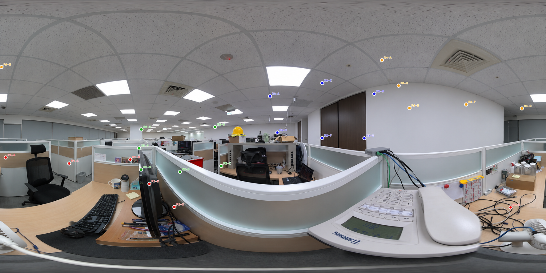
360° panoramic cameras provide full-scene visibility from a single camera point. For monitoring applications, this wide field of view is valuable because it allows operators to observe a larger environment with fewer blind spots.
However, in practical use, monitoring does not always happen directly on the full panoramic image. Operators may open a local view to inspect a specific area. AI models may process a cropped region for object detection. Users may add markers, annotations, or event points inside a selected view.
For these functions to be useful in a 360° monitoring system, the local information must be mapped back to the original panoramic image coordinate system. This allows the system to maintain a consistent spatial reference between the full panoramic scene and its local views.
The Challenge: Connecting Local Views with the Full Panoramic Image
A standard camera image has a fixed frame. If an object is detected at a certain pixel position, that position belongs directly to the same image plane.
A 360° panoramic image is different. The image represents a surrounding spherical scene projected onto a flat surface, often in an equirectangular format. In this format, the horizontal axis corresponds to the viewing direction around the camera, while the vertical axis corresponds to elevation.
When a local view is generated from a 360° image, it is essentially a perspective view looking toward a specific direction inside the panoramic sphere. This local view has its own center direction, field of view, zoom level, and image coordinate system.
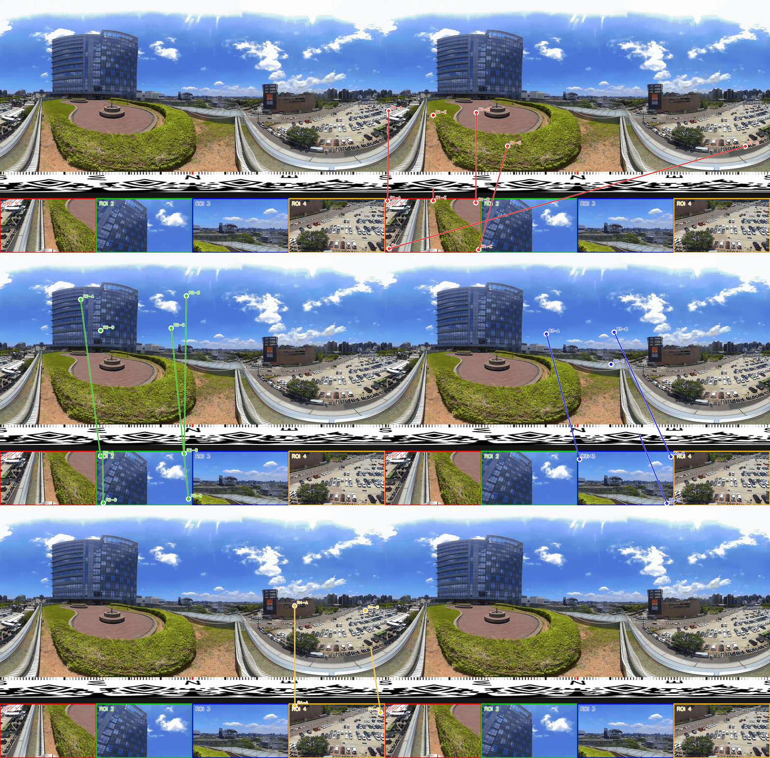
This creates a coordinate-mapping problem. If a user selects a point inside the local view, or if an AI model detects an object inside that local view, the system needs to calculate where that point or detection belongs in the original 360° panoramic image.
Without this mapping, local views become disconnected from the full scene. With accurate mapping, local inspection, AI detection, and panoramic awareness can work within the same spatial reference.
What Local View Mapping Means
Local view mapping is the process of converting coordinates from a local perspective view back to the full 360° panoramic image.
In a monitoring system, this can apply to several types of information:
- A user-clicked point inside a local view
- A bounding box generated by an AI detection model
- A manually added annotation or event marker
- A selected region of interest
- A replay or review point linked to a previous event
The purpose is to preserve the relationship between local detail and full-scene context. For example, if an AI model detects a person in a local view, the system should be able to display that detection at the correct position in the panoramic image. If an operator marks a specific machine or doorway in a zoomed view, that marker should still correspond to the correct location in the full 360° scene.
This is especially important for AI detection, event review, remote monitoring, and multi-view navigation.
Panoramic Image Coordinate System
A common 360° image format is the equirectangular projection. In this format, the entire spherical scene is unwrapped into a rectangular image.
The horizontal coordinate usually represents the azimuth angle, or yaw, around the camera. A full horizontal range corresponds to 360°. The vertical coordinate represents the elevation angle, or pitch, from the top to the bottom of the sphere.
In simplified terms:
- Horizontal movement in the panoramic image corresponds to looking left or right around the camera.
- Vertical movement corresponds to looking up or down.
- Each pixel in the panoramic image can be related to a direction in 3D space.
Because of this structure, mapping between local views and the full panoramic image requires more than a simple 2D crop calculation. The system must account for spherical projection, viewing direction, field of view, and perspective transformation.
Local View Coordinate System
A local view is a perspective view generated from the panoramic image. It behaves more like a normal camera view, showing only a selected direction and field of view from the 360° scene.
A local view usually includes parameters such as:
- Center yaw: the horizontal direction the local view is facing
- Center pitch: the vertical direction the local view is facing
- Field of view: how wide or narrow the local view is
- Output width and height: the local view image size
- Pixel coordinates: the position of a point inside the local view
When a point appears inside the local view, its pixel coordinate is only meaningful within that local image. To restore it to the panoramic image, the system must first interpret that pixel as a viewing ray, then project the ray back to the 360° image.
Coordinate Mapping Workflow
The mapping process can be understood as a sequence of transformations. The exact implementation may vary depending on camera model, projection method, lens calibration, and software architecture, but the general logic is similar.
- Convert Local Pixel Coordinates to Normalized View Coordinates
The first step is to convert a point from local pixel coordinates into normalized coordinates relative to the center of the local view.
For example, if the local view has a width and height, a point inside that view can be represented by its horizontal and vertical offset from the center. This normalized position tells the system where the point lies within the perspective view.
A point near the center of the local image corresponds to the local view’s center direction. A point near the edge corresponds to a direction farther away from the center, depending on the field of view.
- Convert Normalized View Coordinates to a 3D Direction Vector
After the local point is normalized, the system converts it into a 3D direction vector. This step uses the local view’s field of view and perspective projection parameters. The normalized 2D point is treated as a ray extending from the camera center into the 3D scene.
The local direction is then rotated according to the local view’s center yaw and pitch. This produces a direction vector in the panoramic camera’s coordinate system. At this stage, the system is no longer only working with a pixel position. It is working with a spatial direction inside the 360° scene.
- Convert the 3D Direction Vector to Panoramic Coordinates
Once the 3D direction vector is known, the system can convert it back into spherical angles, usually yaw and pitch. These angles are then mapped to the corresponding pixel coordinates in the equirectangular panoramic image.
The result is a position in the original 360° image that corresponds to the selected point, annotation, or AI detection in the local view.
For a bounding box, this process may be applied to key points such as corners or sampled boundary points, depending on how accurately the detection area needs to be represented on the panoramic image.
Mapping AI Detection Results Back to the Full Scene
AI detection models often operate on standard perspective images or cropped regions. This is useful because many AI models are trained on conventional image formats and may perform better when analysing a local view instead of a distorted panoramic image.
However, if the detection result remains only inside the local view, operators may lose the full-scene context. The system needs to know where that detection belongs in the panoramic image.
For example:
- A person detected in a restricted zone should be shown at the correct location in the full 360° scene.
- A PPE detection result should remain linked to the work area where it occurred.
- A vehicle or object detected near a facility boundary should be placed back into the wider site context.
- An alert generated from a local AI model should be reviewable in the panoramic image and playback timeline.
Coordinate mapping allows AI detection results to be connected back to the panoramic spatial reference. This helps operators verify alerts, understand surrounding conditions, and review incidents with better context.
Handling Bounding Boxes and Detection Regions
Mapping a single point from a local view to the panoramic image is relatively straightforward. Mapping a bounding box or detection region requires additional consideration.
A bounding box in a local perspective view is rectangular. After projection back to the panoramic image, the corresponding region may not remain a perfect rectangle because the panoramic image uses spherical projection.
Depending on the application, the system may choose different methods:
- Map the center point of the bounding box to indicate the object location
- Map all four corners of the bounding box
- Sample multiple points along the bounding box boundary
- Convert the region into a polygon on the panoramic image
- Use the mapped center point for event markers while keeping the original local detection view for visual confirmation
The appropriate method depends on the required precision, interface design, and AI application. For event alerting, a center marker may be sufficient. For visual overlay or detailed review, a more accurate projected region may be needed.
Why Coordinate Mapping Matters for Monitoring Applications
Coordinate mapping is not only a mathematical conversion. In monitoring systems, it directly affects how operators understand and respond to events.
Accurate mapping can support:
- Event localization in the full panoramic image
- AI detection verification
- Consistent annotation and marker placement
- Local view and full-scene navigation
- Incident replay with spatial context
- Reduced confusion between similar local views
- Better integration between AI results and visual monitoring workflows
For remote operators, this is especially important. A detection result should not only say what was detected. It should also show where it happened in relation to the surrounding environment.
Supporting AI-Enabled Monitoring Across Different Sites
For monitoring applications, coordinate mapping becomes especially useful when local views, AI detection results, and event markers need to remain connected to the full 360° scene.
In smart factories and industrial sites, this can help operators connect local detections or annotations with production areas, entrances, equipment zones, storage areas, and safety regions. In data centers and equipment rooms, local views may focus on racks, aisles, devices, or access points, while the panoramic image helps preserve overall location context. For construction sites, campuses, public spaces, remote facilities, and robotic patrol systems, the same mapping logic can support event localization, incident review, and more intuitive remote monitoring.
Cupola360’s panoramic vision platform is designed to support this connection between full-scene visibility and local-view interaction. By maintaining the relationship between local views and the original panoramic image, Cupola360 helps turn 360° video into a spatial reference layer for AI-enabled monitoring and remote inspection workflows.
This allows AI detections, annotations, and event markers to be reviewed not only as isolated results, but as part of the wider site context.
Conclusion
360° panoramic cameras provide wide-area visibility, but effective monitoring requires more than a full image. Local views, AI detection results, annotations, and event markers need to remain connected to the original panoramic coordinate system.
Coordinate mapping provides this connection. By converting local view coordinates into 3D directions and projecting them back to the panoramic image, the system can preserve spatial context across local inspection, AI detection, and full-scene monitoring.
For AI-enabled and remote monitoring applications, this makes 360° vision more than a wide-angle view. It becomes a spatial reference layer that helps operators understand where events happen, how they relate to the surrounding scene, and how to respond with better context.
Related Articles